


|
Streetlights require some kind of manual or automatic switching device to enable them to switch on and off. Originally, streetlights were turned on and off manually by a 'Lamplighter', but over time, all sorts of automated methods of switching have been invented and used.
Manual switching Normally mounted some 8ft-10ft from ground level, these electric switch boxes were simple but rugged switch devices that had to be operated manually by a 'Lamplighter'. The switch would be activeted by the 'lamplighter' reaching up with a wooden pole with a hook or loop fixed onto the end of it. The external rocker-switch would them be pulled down into either the on or off position to operated the lamp above. Click here for images.
Timeswitches and 'Calendar' Time-switches Until about 25-30 years ago, 'time-switches' were the accepted method of switching streetlighting on and off. Early examples were clockwork and needed to be regularly wound, as well as being manually re-set every couple of weeks to allow for the variances in lighting up times during the year. Over the years automatic electro-mechanical clocks were developed that were designed to allow for the variance in lighting-up times, these were known as 'calendar-time-switches'. However, over the last quarter of a century, calendar-time-switches have all but disappeared from use in streetlighting. Today, the vast majority of streetlights in the UK, and elsewhere around the world, are controlled by light-sensitive photocell controlled switches; a far more cost effective and reliable method of controlling streetlights.
Rythmatic (Ripple) control switching 'Rythmatic'
or 'Ripple' control was an automated
switching system used in the post-war period and during the 1950's by some local
authorities in
Britian. It enabled the 'switching' of street lighting over
large areas, to be controlled from a single unit at an electric sub-station.
Individual street lights, or groups of street lights were fitted with a
frequency sensitive tuned relay. When it was time to switch the streetlights
on, a burst of high frequency signal was sent down the mains supply from the
sub-station, and these relays detected the signal and closed the circuit to the
lamp. When it was time to switch off the streetlights another burst was sent.
Sometimes the HF signal generator at the sub-station was controlled by a master
time-switch, or sometimes was even operated manually. This switching system was
probably the forerunner of the telephone control switching systems used today.
My sincere thanks to Mike Docherty for providing the technical information.
Photocell control Sometimes known as PECU's (photoelectric control units), Photocells are electronic light-sensitive devices usually mounted on the top of the lantern or sometimes on the column top. These devices measure the light level, and as daylight begins to fail and light level drops, the photocell will sense this and activate the switch/controller, turning the lamp on. Likewise, when the light level increases again, the photocell will sense the increasing levels of light and will extinguish the lamp. Various photocells are available that react differently to differing light conditions, so that the optimum performance and economy can be obtained from streetlighting during lighting-up times. The photocells are also designed to have a delayed reaction to rapidly changing light levels (such as rain storms in daylight hours), so that they don't repeatedly switch the lighting on and off under those conditions. Like most components, photocells will eventually fail during their service life, but when they do, they are designed to fail 'on'. You may have seen streetlights lit during the day (day-burning); quite often the problem is caused by a failed photocell. There are two basic types of photocell: one-part photocells and two-part photocells:
In a one-part photocell switch, the photocell and control switch are integral to one another. The photocell unit fits directly into the control switch, known as a NEMA socket (National Electrical Manufacturers Association), normally mounted on top of the lantern. The photocell is fixes into the NEMA socket by means of a bayonet type fixing, so if it fails or needs replacing it's as easy to change as a light bulb. The advantage of these types of photocell controlled switches is that they are compact and can be easily accommodated within the structure of the lantern.
Two-part cells differ in that the photocell and switch are not as one; normally the photocell is situated in the top of the lantern, but the control switch may be located some distance away, in the base of the lamppost column for instance. Click here for image.
The future? Intelligent Management (IM) control systems. IM is a control system that relies on radio waves to
communicate from a base station via a radio transmitter to a transmitter/receiver
node mounted on
the top of each individual lantern. The software in the system not only allows
the on/off switching when required, but also has the capability of dimming
lanterns by activating a dimming circuit within the lantern's electronic
ballast, e.g. dimming of streetlighting in the early hours of the morning when the
roads are empty. This has the potential of considerable cost savings on current
energy consumption levels. IM also enables information on the lamp life of individual
lanterns to be relayed back to the control centre, informing the operator
whether or not any given lantern is operational. Therefore unnecessary
dayburning of lamps can be prevented, and costly nighttime inspections of
installations can be avoided.
Another major advantage of the system is that it can be implemented into an existing installation and does not require additional ground works. However, if a dimming capability is required from the installation, suitable replacement lanterns with a built-in dimming capability will need to be used. All IM installations require a radio transmitter base station (and possibly sub-stations) to be installed at suitable locations, which means that the initial cost of installing an IM system could prove prohibitive. Update: I understand that Mayflower Intelligent Management Systems (MIMS) have recently developed an IM control system that has the capability of dimming conventionally ballasted lanterns with the use of a special adapted transmitter/receiver node. My thanks to Dave Bisby of Sheffield City Council for this information.
Here are some examples of the switches and photocells held in the collection:
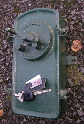
BLEECO No243HS manually operated '2-pole fused' switch mounted in a 'Bombay' watertight cast iron box for either pole or wall mounting. The car keys give a sense of scale.
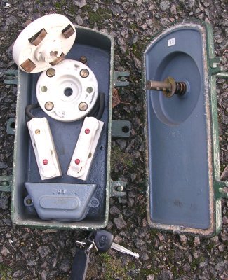
With the box open; from top to bottom, the porcelain spring loaded contact discs, the two porcelain fuse holders, and the cast iron sealing chamber. Note the asbestos door seal.
A 'REVO' manually operated 'rocker' switch for conduit mounting. These types of swiches were usually mounted between the column top and the bracket supporting the lantern. The switch is in acquired condition, and aside from the bent arm on the rocker switch, it's complete and is an excellent candidate for a complete rebuild and refit to a suitable REVO bracket from the collection.
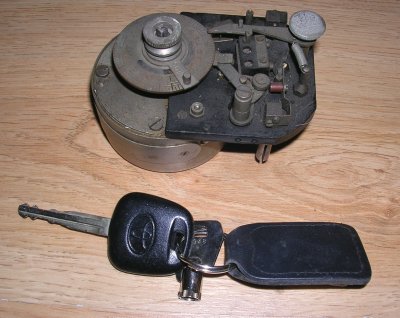
Time-switches (early non-Calender types) Hand wound 'clockwork' Venner BF/43 250v, 5amp time-switch (minus its outer case), Circa 1920's. These early devices were for 24-hour switching, but had no automatic adjustment for seasonal variances in lighting up times, so had to be manually reset every couple of weeks. The square ended spindle sticking out from the centre of the clockwork mechanism is where the key would engage to windup the spring powered motor. The car keys show how small these early devices were.
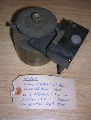
Minus its outer case, a Venner MPX 'electric' 200-250v, 50Hz, 10 amp time-switch (24hour, non-calander). Saved from Oldham M.B.C's Uppermill Council Depot in 1974 by Dorron Harper. This early electric time-switch had orignally been new to Saddleworth U.D.C. in about 1930.
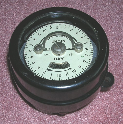
Horstmann Y-MK2 200v-250v 50Hz 30(12)A Calendar Time-switch
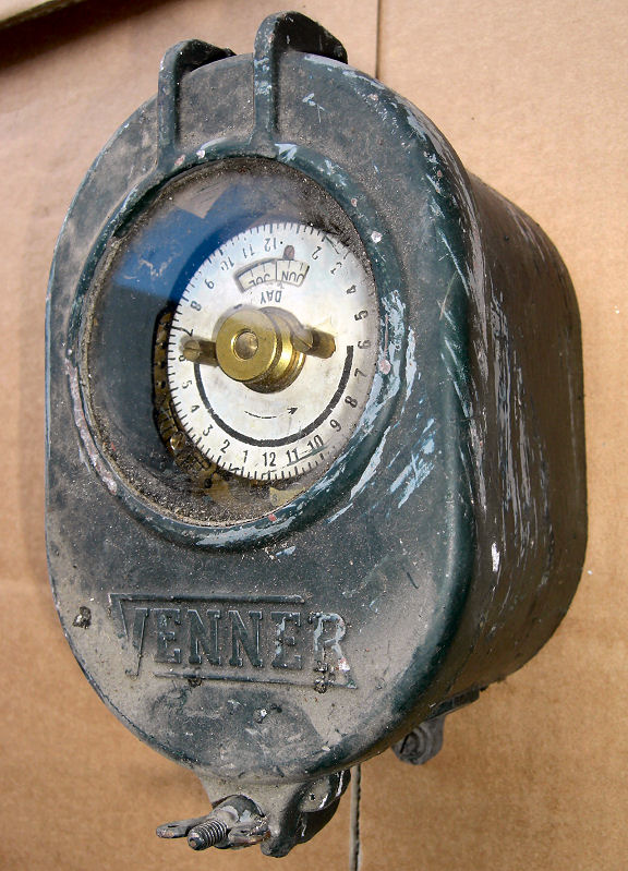
Venner TJSSP Timeswitch, enclosed
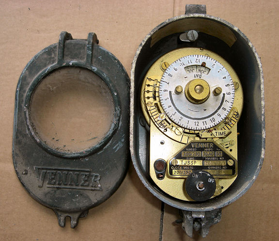
Venner TJSSP Timeswitch, case cover removed revealing the electric clock and switching device
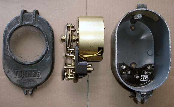
Venner TJSSP Timeswitch dismantled, showing contact pins that locate into the back of the casing
1960's Sangamo S251 20Amp 240v 50Hz Calendar Time-switch
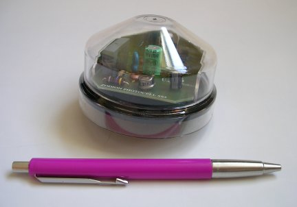
Cableform Zodion SS5 Photocell (minus its NEMA socket)
Awaiting image Cableform Zodion SS6 Photocell (minus its NEMA socket)
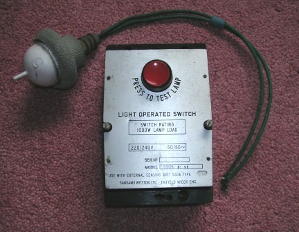
Sangamo S305 control switch and light detector. The 'S' on the photocell detector indicates South, and is the direction that the 'S' needs to face when the detector is mounted on top of the lantern, so correctly aligning itl for sunrise and sunset. The spike on top of the detector is to prevent birds from perching on top of the dectector and covering it in droppings, which would eventually block out the light and stop the photocell from operating correctly. The control switich would be mounted inside the column.
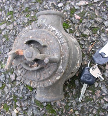
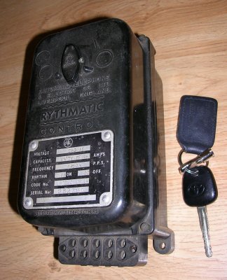
Ripple or Rythmatic control switching An ATE (Automatic Telephone and Electric Co Ltd, of Liverpool), 250v AC 1450 Hz Rythmatic Control Switch (Rhythm 0.66 on / 1.00 off). This Bakelite encased unit dates from the late 1940's and came from Lytham St Annes. Car keys used to give an idea of scale. |
|
|

Copyright(c) 2005 Claire Pendrous. All rights reserved.
Please note that all pictures are by Claire Pendrous, or are part of the Claire Pendrous photographic collection unless otherwise stated; none of these images can be copied without obtaining prior permission.